I’ve found myself in need of a large sliding sensor. Many solutions exists for small sizes, inspired from ipod’s great capacitive wheel (DIY ones). However, when it comes to large size sensors, I found myself in lack of good references. Here is how I made a 15cm wide capacitive touch wheel.
Materials
I’ve used the arduino Leonardo as I know it well and already knew how to use it as a joystick. It’spossible to do capacitive reading with the bare board using the CapSense library. However the sensitivity/stability wasn’t quite high enough and I used an Arduino Shield embedding the MPR121 controller.
Design
The main thing to take into account with capacitive sensors is electrode surface. It’s what will make your sensor’s Gain. While it’s possible to tune capacitance by adding a small capacitance in parallel as advised for the CapSense Library, it will just lengthen the measure process. It’s sometimes necessary, especially when not using a controller designed for rapid Discharge Analog Reads like the arduino. With a dedicated controller however, I’ve seen no reason to tune the sensor this way. THis leaves us with the bare truth :
Nothing will improve your electrode's sensitivity except a better design.
Dedicated controller datasheets contain some advices on how to design good electrodes. Read the internet if you want to make your own idea, but here is what I learned :
- Thickness is not that important. If you have a choice, thin is better.
- Any nearby metal part (including wiring copper) will cause perturbation proportional to size and proximity.
- Space between electrodes should be exactly the width of one finger. There is no need to detect the finger on 3 electrodes at a time. A space of more than a finger’s width will create dead zones.
Large copper surfaces on a standard PCB, as far away as possible from the wiring seems to be a good solution. However we should take care not to fill the PCB with copper as it would cause interferences.
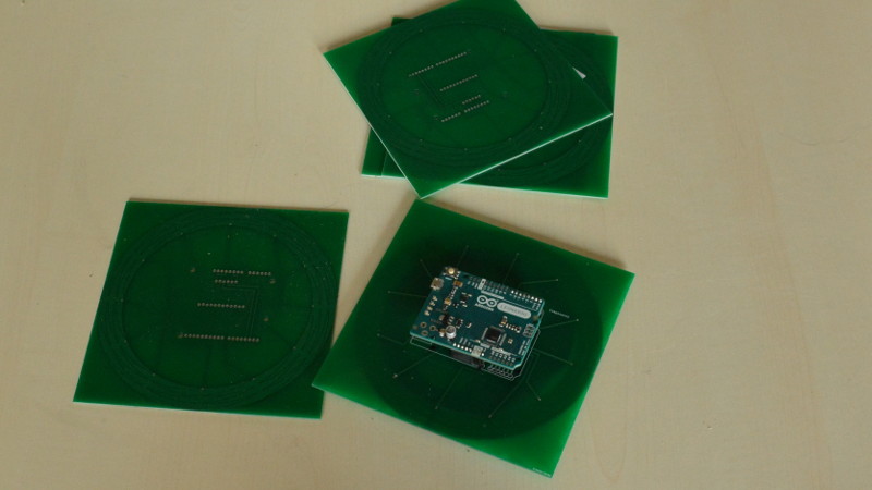
Here is the final design I made :

It’s largely inspired by the original patent from 1981 and further designs of small wheels, except it has maximized electrodes count as 3 electrodes are clearly not a good fit for such a large design.
If you want to design your own, with a different electrode count for example, here is how I made it :
Draw the layout
I made this with a CAD software. Created 1 electrode and once I was satisfied with the design, just applied a circular symmetry to copy it.
Convert to svg
Your PCB software might support other formats but mine only accepted SVGs. I did it in 2 steps : Convert from CAD proprietary software to DXF (exports only the outline). Then open the dxf in Inkscape and fill zones in black.
PCB manufacturing
I embedded the svg in a Fritzing project, added some wiring. Be careful with that, it’s dependent on your shield’s wiring.

I found it on banggood, but any similar arduino shield should work fine. It should even be quite easy to work with a bare controller soldered on the board as the design is really simple, if you have the resources to solder it.
Once the project is setup, simply export it as gerber files and contact any prototype PCB maker to put it on production.
The final Fritzing project and Gerber Export. Be careful with that : PCB manufacturers often have small differences in how the gerber files should be.
Here are mine, done on seeedstudio :
Code
I was not able to find code on finger position interpolation for this type of sensors. Fortunately, it was not too difficult to do. However it required some fine tuning to work smoothly.
We will use the unmodified code of Adafruit’s MPR121 Library. Internally it uses the Wire libray. You’ll need to install both.
#include <Wire.h>
#include <Joystick.h>
#include <MPR121.h>
#include <Coordinates.h>
We will later modify Adafruit’s code to tune results.
the best way to get results out of a slider is to do a center of mass calculation. However we don’t need a (x,y) position but an angle and an amplitude. It’s easy enough once you have fast polar <-> cartesian coordinates conversions. The coordinates library does exactly that.
Cells are represented as vectors, with an angle corresponding to their position on the circle and a radius corresponding to the sensed signal. MPR121’s filtered results for untouched cells are generally -4< res <=0 (because of a bit shift in the library code) so we filter out negative results.
The code is quite simple :
Init
#include <Wire.h>
#include <Joystick.h>
#include "MPR121.h"
#include <Coordinates.h>
// You can have up to 4 on one i2c bus but one is enough for testing!
Adafruit_MPR121 cap = Adafruit_MPR121();

#define THRESHOLD 3 //above this radius, it's a "touch"
#define SENSOR_COUNT 12
//Most filtering is done by the shield, but we do some stability improvement
float lastAngle;
float filteredMean = 0;
float filteredAngle = 0;
int data[SENSOR_COUNT ];
Coordinates position = Coordinates();

void setup() {
  Serial.begin(9600);
  Joystick.begin(true);
  // Default address is 0x5A, if tied to 3.3V its 0x5B
  // If tied to SDA its 0x5C and if SCL then 0x5D
  if (!cap.begin(0x5A)) {
    Serial.println("MPR121 not found, check wiring?");
    while (1);
  }
  Serial.println("MPR121 found!");
}
Calculate angles
It’s just some diff with a test to stay in the (0..2PI) interval.
float angleDiff(float a, float b){
  if(abs(b-a) < PI ){
    return b-a;
  }else if(a <b) {
    return 2*PI-b+a;
  }else{
    return 2*PI+b-a;
  }
}
Acquire data
It’s now time to acquire position from our sensor :
void loop() {
  int i;
  float x = 0,y = 0;
  float newAngle;
  int m;
  //Get vectors
  unsigned long start = millis();
  for(i=0;i<SENSOR_COUNT ;i++){
    m = cap.baselineData(i) -cap.filteredData(i);
    if(m<0) m = 0;
    position.fromPolar(
      m, PI*2*i/SENSOR_COUNT
    );
    //Add them
    x += position.getX();
    y += position.getY();
  }
  position.fromCartesian(x,y)
  Serial.println(position.getAngle());
}
It’s now possible to start tracking a finger’s position by logging the result of position on each loop().
Filtering
I’m still working on this part. The goal is to make a minimal overhead filter that allow a reliable finger speed interpolation.
For now I’m just using a simple running average, which is not really worth sharing.
Usage
We made ourselves an easy way to detect touch : If radius is large enough, one or many adjacent cells are touched.

If a finger is in the middle of 2 cells, the addition of vectors will give an accurate result as expected. However if the user uses two fingers, results can be quite funny. I did not identify it as a problem as in term of UX, every user I’ve seen immediately identify it as a 1 point touch device, so they are not deceived when it fails if they put 2 fingers.
Optimizing
While the MPR121 library is really good, it does not allow us to customize the controller’s registers. How is that a problem?
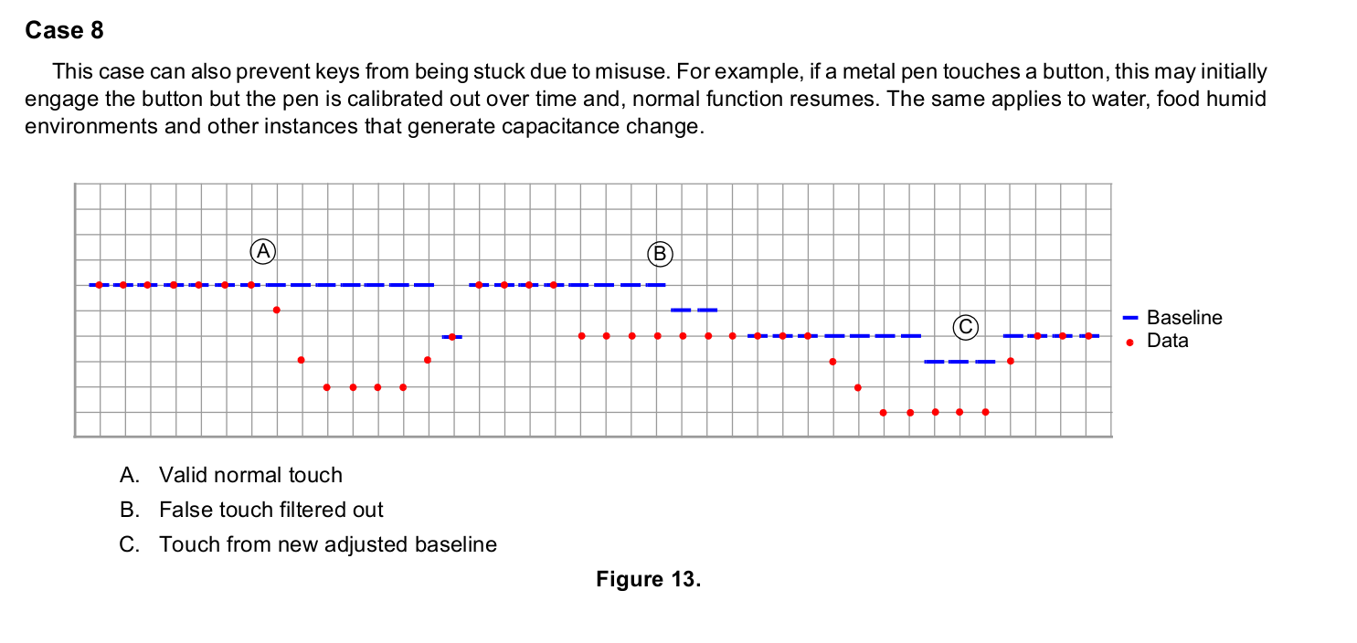
If we log the filtered results, we will notice a bump after a touch. That’s because a prolonged touch on the sensor will make it think the electrode capacitance has changed. It’s designed to be able to react to fast environment changes at that’s good, but it’s not what we want here.
MPR121’s Application note 3891 gives us some examples on how to tune registers to have the best filter configuration for our use case.
We will modify Adafruit_MPR121.cpp to push customized values into registers. Fortunately Adafruit’s code is easily readable.
//See MPR121_datasheet.pdf page 12. Refer to AN3891.pdf to see how to configure
writeRegister(MPR121_MHDR, 0x01); //Rising Maximum Half Delta
writeRegister(MPR121_NHDR, 0x02); //Rising Noise Half Delta
writeRegister(MPR121_NCLR, 0x20); //Rising Noise Count Limit
writeRegister(MPR121_FDLR, 0x01); //Rising Filter Delay Count Limit

writeRegister(MPR121_MHDF, 0x01);//Falling Maximum Half Delta
writeRegister(MPR121_NHDF, 0x00);//Falling Noise Half Delta
writeRegister(MPR121_NCLF, 0xF0);//Falling Noise Count Limit
writeRegister(MPR121_FDLF, 0x05);//Falling Filter Delay Count

writeRegister(MPR121_NHDT, 0x00);//Touchig Noise Half Delta
writeRegister(MPR121_NCLT, 0xF0);//Touchig Noise Count Limit
writeRegister(MPR121_FDLT, 0x05);//Touching Filter Delay Count

writeRegister(MPR121_DEBOUNCE, 0);
writeRegister(MPR121_CONFIG1, 0x3F); // charge current
writeRegister(MPR121_CONFIG2, 0x40); // encoding time, period
Detail of register values and function is available in the datasheet.
Once it’s done, copy Adafruit_MPR121.cpp and Adafruit_MPR121.h in your arduino project’s folder to have a local copy. In the head of your .ino, replace the incldue with include "Adafruit_MPR121.h" to use the local file.
End result
I’m pretty proud of the result. The sensed signal is really stable when using a bare PCB.
However as soon as there is a significant protection layer, it swiftly decrease to be somewhere between acceptable and really bad. I’m still working on finding an adequate coating, resistant enough while as thin as possible.